Machine Information
Miyano BNJ-51SY6
The BNJ-51SY6 includes the new, more powerful Fanuc 0i-TF control that comes standard with a multitude of CNC features that were not available on previous generations of the control. In addition, 8-Station Sub Turret makes free simultaneous machining Front-Back.
Fixed headstock type CNC automatic lathe
7-cutting axes (X1, Z1, Y1, X2, Z2, C1, C2)
Two spindles
Two turrets
One Y-axis slide
25 Nm twelve revolving tool stations (main turret)
Eight tool stations (turret No. 2)
2" diameter bar capacity
3.9" work length
Functions
Standard NC functions
- 10.4"color LCD
No of registered programs: 800
Decimal point input
Manual pulse generator
Memory protect
Polar coordinate interpolation
Programmable data input (G10)
C-axis control (SP1/SP2)
Superimposed control A
Chamfering/ Corner R
- Tool nose R compensation
Background editing
Synchronous mixed control
Operating time/ Parts No. display
Multiple repetitive canned cycle (G70-G76)
Continuous threading
Canned cycle for drilling
Tool life management system
Variable-lead cutting
Rigid tap function (Spindle & Revolving tool)
- Circular interpolation
Custom macro
Handle retrace function
Polygon cutting
Synchronized function
Dual check safety
Network I/O function
Reference position setting
Helical interpolation, RS-232C
Functions
Other functions
- Splash guard interlock
Coolant
Pneumatic unit
Machine light
Non-fuse breaker
SP2 Work ejector & inner high pressure coolant
Chuck close confirmation
- Total & preset counter (Custom menu)
Cut-off confirmation
High pressure coolant
Revolving tool (HD2)
Spindle brake
Air blow
Parts catcher & Parts conveyor
- Chip conveyor
Coolant level switch
Bar feeder interface
Signal tower
Automatic power shut-off
Thermo revision
Accessories
Optional Accessories
- Drill breakage detector
Part carrier
- Chip box
- Tool holder, tools, etc.
Specifications
Machine Specifications
| ITEM | BNJ-51SY6 |
|---|---|
| Maximum machining length | 100 mm |
| Diameter of standard cutting: Spindle No. 1 | 51 mm Dia. |
| Diameter of standard cutting: Spindle No. 2 | 42 mm Dia. |
| Chuck size: Spindle No. 1 | 6 inch |
| Chuck size:Spindle No. 2 | 5 inch |
| Number of spindles | 2 |
| Spindle speed range: Spindle No. 1 & 2 | 5,000 rpm |
| Inner diameter of draw tube: Spindle No. 1 | 52 mm Dia. |
| Inner diameter of draw tube: Spindle No. 2 | 43 mm Dia. |
| Collet chuck: Spindle No. 1 | H-S22 |
| Collet chuck: Spindle No. 2 | H-S16, DIN171E |
| Power chuck: Spindle No. 1: | 6" thru-hole chuck |
| Power chuck: Spindle No. 2: | 5" thru-hole chuck |
| Number of turrets: | 2 |
| Type of turret: Turret No. 1 | 12 station turret |
| Type of turret: Turret No. 2 | 8 station turret |
| Shank height of square turning tool | 3/4" Sq. |
| Diameter of drill shank | 1" Dia. |
| Revolving tools: Number of revolving tool (Turret No. 1) | Max. 12 |
| Revolving tools: Number of revolving tool (Turret No. 2) | Max. 4 |
| Revolving tools: Type of revolving tool (Turret No. 1) | Single clutch |
| Revolving tools: Type of revolving tool (Turret No. 2) | Simultaneous drive in all positions |
| Revolving tools: Tool spindle speed range (Turret No. 1) | 6,000 rpm |
| Revolving tools: Tool spindle speed range (Turret No. 2) | 3,000 rpm |
| Revolving tools: Machining capacity Drill (Turret No. 1) | Max. 13 mm Dia. |
| Revolving tools: Machining capacity Drill (Turret No. 2) | Max. 10 mm Dia. |
| Revolving tools: Tap (Turret No. 1) | Max. M12 × 1.75 (S45C-D) |
| Revolving tools: Tap (Turret No. 2) | Max. M6 × 1.0 (S45C-D) |
| Turret slide stroke: X1 axis | 165 mm |
| Turret slide stroke: Z1 axis | 246 mm |
| Turret slide stroke: Y1 axis | 80 (± 40) mm |
| Spindle slide stroke: X2 axis | 85 mm |
| Spindle slide stroke: Z2 axis | 590 mm |
| Rapid feed rate: X1, Z1, X2, Z2 axes | 20 m/min |
| Rapid feed rate: Y1 axis | 12 m/min |
| Motors: Spindle drive (Spindle No. 1 Cs) | 15/ 11 kw (15 min/cont.) |
| Motors: Spindle drive (Spindle No. 2 Cs) | 7.5/ 5.5 kw (15 min/cont.) |
| Motors: Revolving tool drive (Turret No. 1) | 2.2 kw |
| Motors: Revolving tool drive (Turret No. 2) | 0.75 kw |
| Motors: Slide | 1.2 kw (X1, Z1, Y, X2, Z2) |
| Motors: Hydraulic oil motor | 2.2 kw |
| Motors: Lubricating oil motor | 0.004 kw |
| Motors: Coolant pump | 0.25 kw × 1, 0.18 kw × 1 |
| Motors: Turret index motor | 0.75 kw |
| Power supply: Voltage | AC 200/ 220 ±10% 50/ 60 Hz ±1% |
| Power supply: Capacity | 33 KVA |
| Power supply: Air supply | 0.5 MPa |
| Power supply: Fuse | 100 A |
| Hydraulic oil tank capacity | 10 L |
| Lubricating oil tank capacity | 4 L |
| Coolant tank capacity | 300 L |
| Machine height | 1,700 mm |
| Floor space | 2,630 × 1,540 mm (without chip conveyor) |
| Machine weight | 11,687 lbs |
Specifications
Machine Specifications
| NC Device | Fanuc FS 0i-TF |
|---|---|
| Controlled axis | Simultaneously controlled axis Max.4 |
| Controlled axis | X1, Z1, Y1, Cs1, A1, A2, X2, Z2, Cs2 |
| Min. input increment | 0.001 mm, 0.0001 inch, 0.001 deg |
| Min. output increment | X axis: 0.0005 mm, Z axis: 0.001 mm |
| Min. output increment | Y axis: 0.001 mm |
| Parts program strage capacity | Total 1MB (2,560m Tape length) |
| Spindle function | Spindle speed S4-digits |
| Spindle function | Constant Cutting speed control (G96) |
| Rapid traverse rate | X1, X2, Z1 axis: 20 m/min |
| Rapid traverse rate | Z2 axis: 20 m/min |
| Rapid traverse rate | Y1 axis: 12 m/min |
| Cutting feed rate | F 3.4 digit per revolution |
| Cutting feed rate override | 0-150% (in 10% increments) |
| Interpolation | G01, G02, G03 |
| Threading | G32, G92 |
| Canned cycle | G90, G92, G94 |
| Work coordinate setting | Automatic Setting, 64 work coordinate setting by the tool position |
| Tool selection | by TAABB at the specified position for each |
| Tool selection | turret tool wear compensation is selected by BB. |
| Direct input of tool position | by measured MDI |
| Input/ Output interface | USB, PC Card slot |
| Automatic operation | 1 cycle operation/ Continuous operation, Single block |
| Automatic operation | Block delete, Machine lock, Dry run, feed hold |
| Automatic operation | Optional block skip |
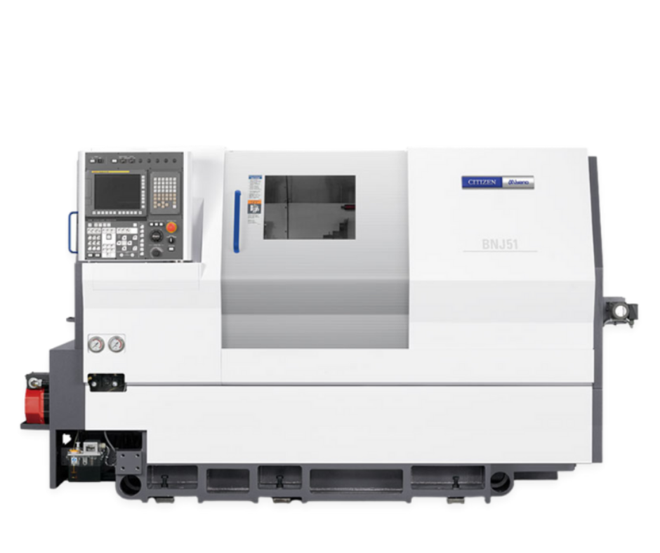
Miyano BNJ-51SY6
Exterior View
